Gatekeeper, Part 1
This week, I’ve been working on an Open-Source electronics project. I’ve never really been successful with electronics, my soldering is sub-par, and it seems easy to release the genie in the form of blue smoke.
Most of my electronics usage is modular. Buy a component, solder on some header pins, if I must and jumper wire them together to make things work. I’ve never really got as far as a deployed system. This week I moved that bar forward.
The Project
A Door Access System that uses backend LDAP authentication, with a front end card scanner with keypad.
The challenge is to keep the secure aspects of the project indoors and only expose the card scanner and keypad to the outside world. This means keeping stuff like relays well away from the insecure outdoors.
It’s worth noting that I’m not intending this to secure the Bank of England. That doesn’t mean it’s not designed to be secure, but it is designed to be appropriately secure.
I’m calling this project Gatekeeper, as I have planned a central controller that authenticates the requests from the doors or “gates”.
The Hardware
On the outside, I’m using a Wiegand keypad with built-in card scanner. Externally this will require three factors to gain access.
- An RFID Card (something you have)
- A PIN (something you know)
- A schedule for your access days/times
Wiegand Keypad - 125MHz rfid card reader and compatible cards
On the inside, we’re going to build the door access controller “gate”.
The Gate
An ESP8266 NodeMCU with plenty of GPIO available.
A Relay to handle the switching of a 12v door strike using the 3.3v logic of our ESP8266
Either a 12v DC power supply or a PoE splitter to provide 12v to the keypad and door strike.
A buck converter to use the same 12v supply to power the ESP8266 at 5v.
A level shifter to handle the keypad 5v logic and convert it to 3.3v logic for the ESP8266.
The Gatekeeper
A Raspberry Pi - this is what does the authentication of all the gates using our backend LDAP server.
The Software
On the gates, I’m using a custom build of Tasmota. I’ve added in Wiegand support and TLS to secure the MQTT traffic.
First time out, Tasmota can seem daunting, but it actually does much of the heavy lifting, meaning I don’t have to write a lot of Arduino code to get it to work the way I want.
On the gatekeeper, I’m using Mosquitto MQTT and a custom python service I have written to process the conversation between gate, MQTT and LDAP.
The Working Principle
In simple terms, this is what is happening:
- A card is scanned and a PIN entered at the keypad.
- The card uid and PIN is handled by the gate.
- The gate sends the uid and PIN to the gatekepper using mqtt.
- The gatekeeper picks up the mqtt payload and asks the LDAP server if it is valid.
- The gatekeeper reports back to the gate using mqtt
- The gate acts on the mqtt response, eg. Open the door or not.
Security Challenges
Do not expose the mechanical and electro-mechanical parts to the outside.
- Ensure you cannot short a circuit or trip it with a magnet to cause the door to open.
Do not have any logic in a device on the outside.
- Keep wires and circuits that make decisions away from the outside.
Wiegand can be hacked. You need something to send a Wiegand signal to do it. These are easily made and equipment can be made to clone the uid of a card. Cards are generally not considered unique. They are manufactured with a large uid, but it is possible that there are two cards the same in the world. By combining the need for a card uid and a pin, we add a requirement for more than just a card. I also add a schedule component in, so that when a card and pin match they are checked to see if they are allowed in at this time of day.
As a further mechanism to handle a stolen card, the gatekeeper records how many failed access attempts have been made by the card and will block it from further attempts, either permanently, or sufficiently long enough to tar pit a potential intruder. Even if you have a device that will hammer the gate with card uid’s and pins, it will not know a reason why it is not working and may even have guessed a valid pin, but failed to understand that the gatekeeper has blocked it from entry. If it doesn’t guess the pin in the first few tries, further attempts will be ignored.
The MQTT traffic is encrypted using TLS and there are ACL’s on the gatekeeper that prevent clients from talking in anything but their own topics. The only device that can post topics to the gates, is the gatekeeper.
The gates are built to be installed in a case and have an anti-tamper switch to detect if it has been opened. Once that happens, the gate tells the gatekeeper, and it is ignored until an administrator resets things.
Gates monitor the position of the doors using a reed switch. If a door is opened and the exit button has not been pressed, or the gatekeeper didn’t authorise it, we need to escalate this as we probably have an intruder who has forced the door open.
The Prototype
First, I built this on a breadboard. I used the USB to give me the 5v required for the keypad logic and have both a 3.3v rail on one side of the breadboard and a 5v on the other. The 4 channel level shifter safely converts the 5v logic to 3.3v logic.
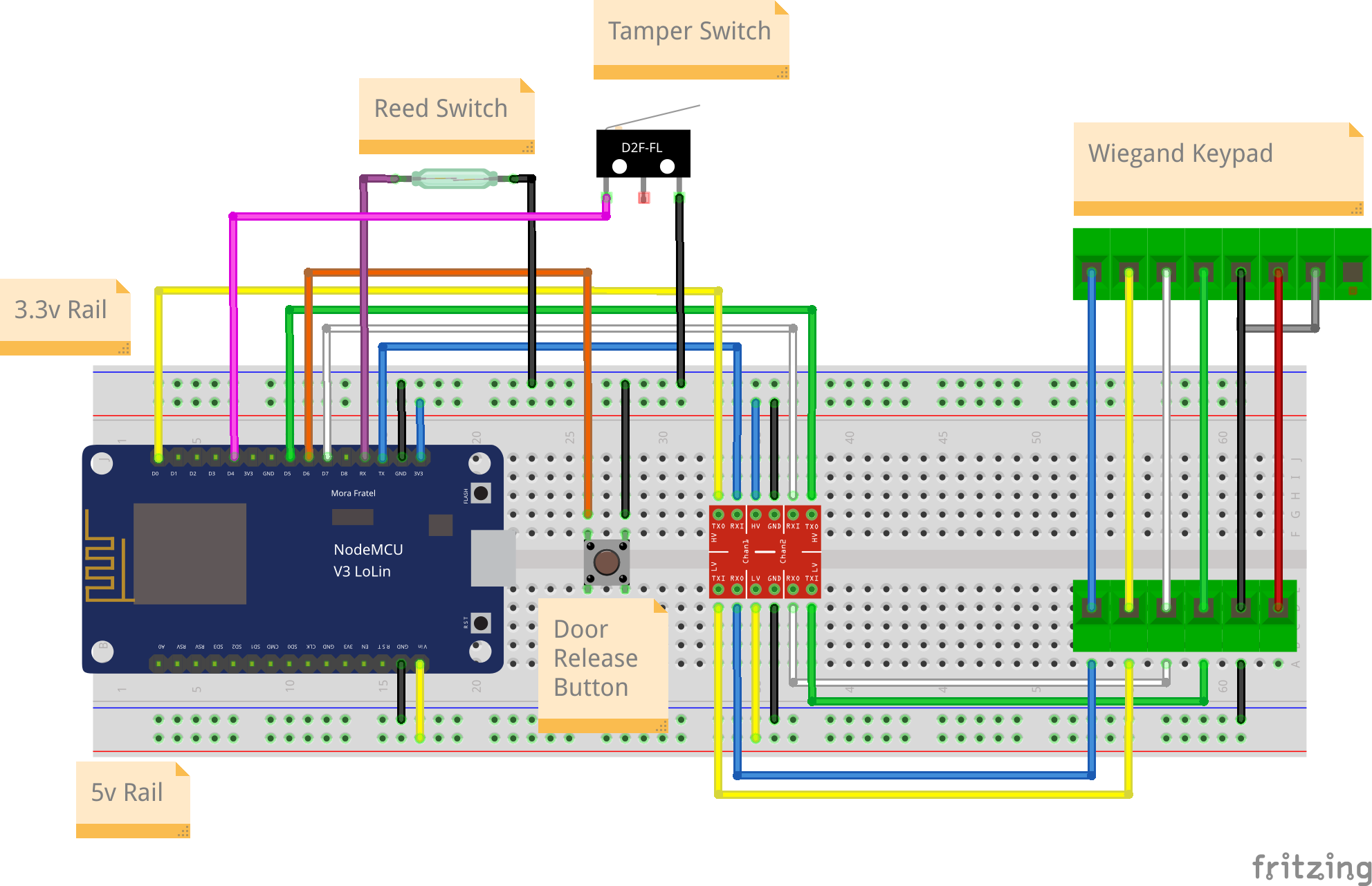
A bit of juggling is required o nthe usage of GPIO pins. Some pins will cause the ESP to fail to boot if they are pulled low. This had a useful side effect for the tamper switch. If the tamper switch is activated, then the ESP will fail to boot.
After I transferred all this onto a strip board, it looked like this:
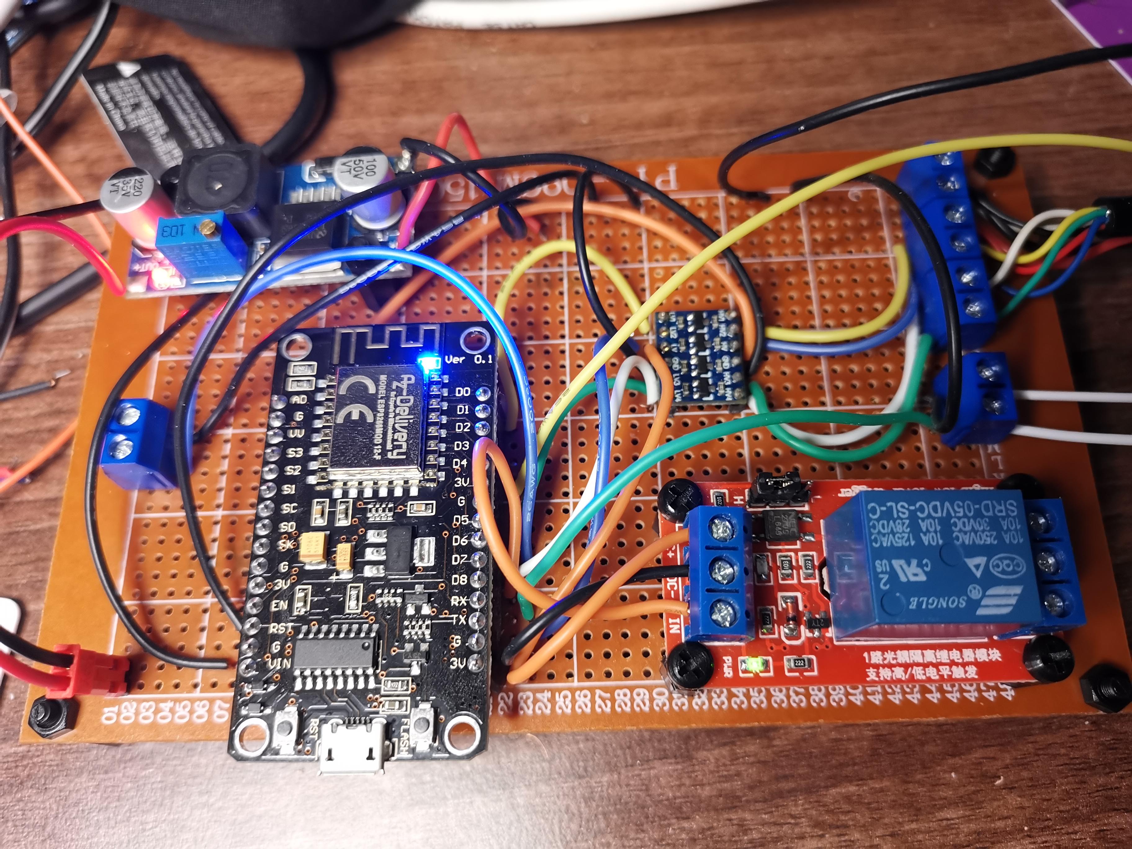
Top left buck convertor converts 12v DC to 5v DC. Bottom right, door strike relay. Bottom left - the ESP8266. Right - the level shifter.
Gate Configuration
Tasmota config
| PIN | Type | ID | Purpose |
| D3 GPIO0 | |||
| TX GPIO1 | Led_i | 1 | Keypad LED (blue) |
| D4 GPIO2 | Switch | 4 | Anti-tamper |
| RX GPIO3 | Switch | 3 | Door Reed Switch |
| D2 GPIO4 SDA (I2C) | |||
| D1 GPIO5 SCL (I2C) | |||
| D6 GPIO12 | Button | 1 | Door Exit |
| D7 GPIO13 | Wiegand D1 | Keypad (white) | |
| D5 GPIO14 | Wiegand D0 | Keypad (green) | |
| D8 GPIO15 | Relay | 1 | Door Open |
| D0 GPIO16 | Relay_i | 2 | Keypad Beep (yellow) |
| A0 GPIO17 |
The gatekeeper also sends a series of instructions over MQTT when a gate is discovered. This sets options to handle switches and buttons.
Backlog SetOption1 1; SetOption13 1; SetOption73 1; SwitchMode3 1; SwitchMode4 2; WebButton1 Door; WebButton2 Beeper; LedState 1; LedMask 0x0001; Rule1 1
Rule1 on switch3#state=1 do publish tele/%topic%/DOOR OPEN endon
on switch3#state=0 do publish tele/%topic%/DOOR CLOSED endon
on switch4#state=1 do publish tele/%topic%/TAMPER ON endon
on switch4#state=0 do publish tele/%topic%/TAMPER OFF endon
on Button1#state=10 do Power1 1 endon
on Power1#state=1 do BackLog LedPower1 on; Power2 on; RuleTimer1 2 endon
on Rules#Timer=1 do BackLog LedPower1 off; Power2 off; Power1 off endon
Anything that triggers a power on will cause Rule1 to start the timer and turn it back off after 2 seconds.
There’s still more to say about this project. I had to build a custom schema for the LDAP server to host attributes for the card, pin and schedules. I installed Mosquitto MQTT and configured it securely, and also wrote a significant amount of python to handle the logic on the Raspberry Pi.
I’ll write the rest of this up in a later article.
To be continued…