With the Gatekeeper project, it was decided to look at wired Ethernet connectivity rather than WiFi. I guess there’s some added security to that, but it does mean finding an ESP with Ethernet - even more preferably with Power over Ethernet (PoE).
Looking around there are a few options. But sadly, some that I can’t get shipped to the UK due to export restrictions - even if they are on a UK domain of an electronic supplier!
I’ve bought a few options to try out, the first of which arrived is the WT32-ETH01.
The WT32-ETH01 doesn’t have PoE. This means I’ll have to use the current method of using a PoE power splitter and a buck controller to reduce the 12V output to 5V - not a major issue as this is how it works with the current ESP8266 where there is no Ethernet.
I checked out the documentation, it looks like I need to take IO0 to GND (for flashing mode), and feed it 5v. The confusion was with what TX/RX pins to use.
I already have a USB FTDI (USB to Serial) cable I can use to flash things with - I just need to connect it up properly.
| WT32-ETH01 | FTDI Cable |
| TX0 | White (RXD) |
| RX0 | Green (TXD) |
| IO0 to GND | |
| GND | Black (GND) |
| 5V | Red (5V) |
| FTDI FT232RL USB | |
| Red | 5V |
| B;ack | GND |
| White | RXD |
| Green | TXD |
| Yellow | RTS |
| Blue | CTS |
Because IO0 and GND are next to each other you can use a jumper for this, I just happen to have a female/female breadboard lead (blue).
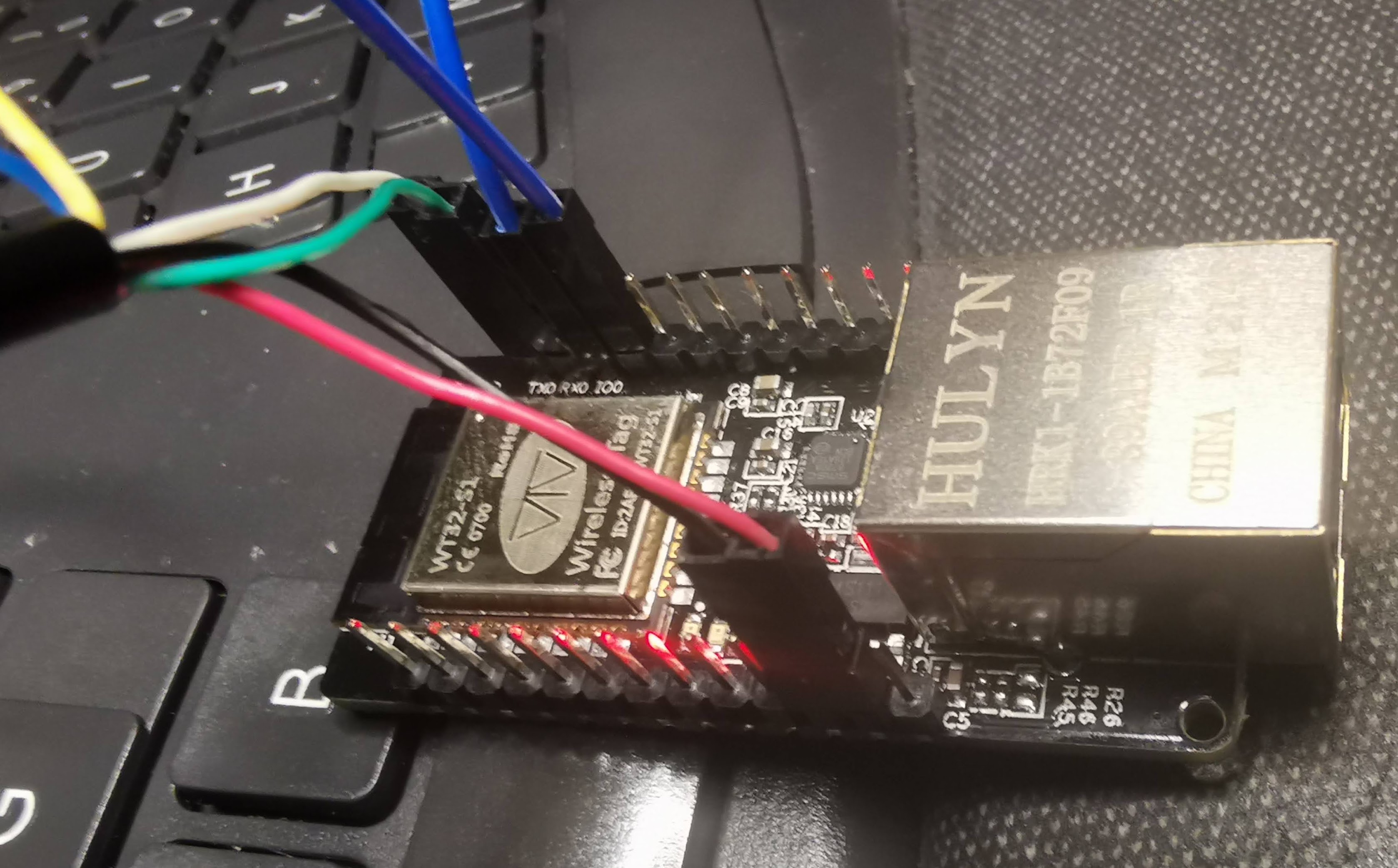
With it all connected, let’s see what we get from esptool.py:
$ esptool.py --port /dev/ttyUSB0 chip_id

esptool.py v3.1
Serial port /dev/ttyUSB0
Connecting.....
Detecting chip type... ESP32
Chip is ESP32-D0WD (revision 1)
Features: WiFi, BT, Dual Core, 240MHz, VRef calibration in efuse, Coding Scheme None
Crystal is 40MHz
MAC: 94:3c:c6:3a:a5:28
Uploading stub...
Running stub...
Stub running...
Warning: ESP32 has no Chip ID. Reading MAC instead.
MAC: 94:3c:c6:3a:a5:28
Hard resetting via RTS pin...
So far, so good!
Compiling the Firmware
You will need to uncomment the “tasmota32” line in platformio_overide.ini to allow for compiling to esp32. To enable Ethernet you’ll also need to follow the notes on the Tasmota page and add the section into user_config_override.h.
#define USE_ETHERNET
  // Wireless-Tag WT32-ETH01
  #define ETH_TYPE          0                    // [EthType] 0 = ETH_PHY_LAN8720, 1 = ETH_PHY_TLK110, 2 = ETH_PHY_IP101
  #define ETH_ADDRESS       1                    // [EthAddress] 0 = PHY0 .. 31 = PHY31
  #define ETH_CLKMODE       0                    // [EthClockMode] 0 = ETH_CLOCK_GPIO0_IN, 1 = ETH_CLOCK_GPIO0_OUT, 2 = ETH_CLOCK_GPIO16_OUT, 3 = ETH_CLOCK_GPIO17_OUT
Writing the Firmware
When writing the firmware, the Tasmota notes say to use the 5V and GND of your FTDI cable - this is, so the PC and ESP share a common ground. However, when running the board live it may need more current than the FTDI USB is capable of, so you should use a separate 5V feed capable of more than 500uA provided by the USB cable. Be careful if you are writing to a live system if the connected pins draw current more than your USB provides.
You may be able to write the firmware by using an external 5V power source, but you will need GND from the FTDI connected to another of the ESP GND pins.
$ esptool.py --chip esp32 --port /dev/ttyUSB0 --baud 115200 --before default_reset --after hard_reset write_flash -z --flash_mode dout --flash_freq 40m --flash_size detect 0x1000 ./Tasmota/tools/Esptool/ESP32/bootloader_dout_40m.bin 0x8000 ./Tasmota/tools/Esptool/ESP32/partitions.bin 0xe000 ./Tasmota/tools/Esptool/ESP32/boot_app0.bin 0x10000 ./Tasmota/build_output/firmware/tasmota32.bin

esptool.py v3.1
Serial port /dev/ttyUSB0
Connecting......
Chip is ESP32-D0WD (revision 1)
Features: WiFi, BT, Dual Core, 240MHz, VRef calibration in efuse, Coding Scheme None
Crystal is 40MHz
MAC: 94:3c:c6:3a:a5:28
Uploading stub...
Running stub...
Stub running...
Configuring flash size...
Auto-detected Flash size: 4MB
Flash will be erased from 0x00001000 to 0x00004fff...
Flash will be erased from 0x00008000 to 0x00008fff...
Flash will be erased from 0x0000e000 to 0x0000ffff...
Flash will be erased from 0x00010000 to 0x00158fff...
Compressed 15872 bytes to 10320...
Wrote 15872 bytes (10320 compressed) at 0x00001000 in 1.2 seconds (effective 107.2 kbit/s)...
Hash of data verified.
Compressed 3072 bytes to 129...
Wrote 3072 bytes (129 compressed) at 0x00008000 in 0.1 seconds (effective 255.7 kbit/s)...
Hash of data verified.
Compressed 8192 bytes to 47...
Wrote 8192 bytes (47 compressed) at 0x0000e000 in 0.2 seconds (effective 409.7 kbit/s)...
Hash of data verified.
Compressed 1347584 bytes to 896322...
Wrote 1347584 bytes (896322 compressed) at 0x00010000 in 79.8 seconds (effective 135.1 kbit/s)...
Hash of data verified.

Leaving...
Hard resetting via RTS pin...
Configure the Template
Copy the template from the Tasmota page and when connected to the ESP admin page, goto Configuration > Configure Other and paste it into the template and tick activate. Then when you restart and revisiting Configuration > Configure Module the available GPIO and pins should be available.
Plugging it in
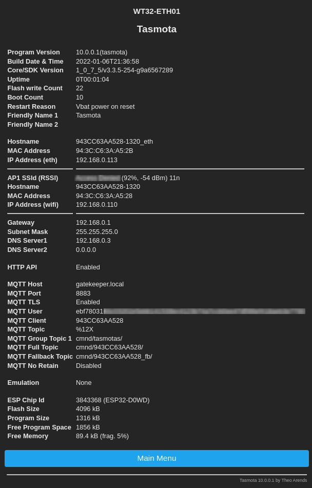
When I connected the Ethernet cable I checked the DHCP server and it showed it came up with two IP addresses, one on Wifi the other wired. I could connect to either of them.
As it states in the documentation, you only see the Ethernet mac and other details if you have the cable plugged in.
References
https://templates.blakadder.com/wireless_tag_WT32-ETH01.html